Category Archives: C

Replace a missing remote control with an Arduino and a laptop

I recently found myself without a remote for my WDTV Live media player, and limited resources to do anything about it – but I did have an Arduino, a breadboard and the local Jaycar had an IR LED.  Controlling IR devices is common practice with an Arduino. I would even be able to hack in functions that didn’t exist on the manufacturer’s remote – like creating a three minute skip by switching to 16x speed for 12 seconds.

The first port of call was to obtain Ken Shirriff’s Arduino IR remote control protocol library – as opposed to communications protocols, of which there are quite a number; did you know the first cut of WiFi included an infrared version? Without the remote, I wasn’t able to record and playback the IR signals sent to the WDTVLive, as you would with a learning remote. I had to find what to transmit from my custom remote. I little googling and I found the WD TV Live infrared remote control codes, which also helpfully reveals that the protocol is NEC.

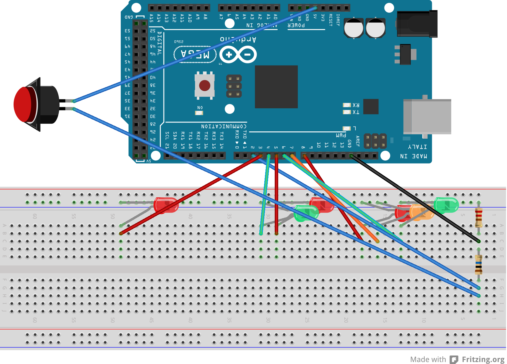
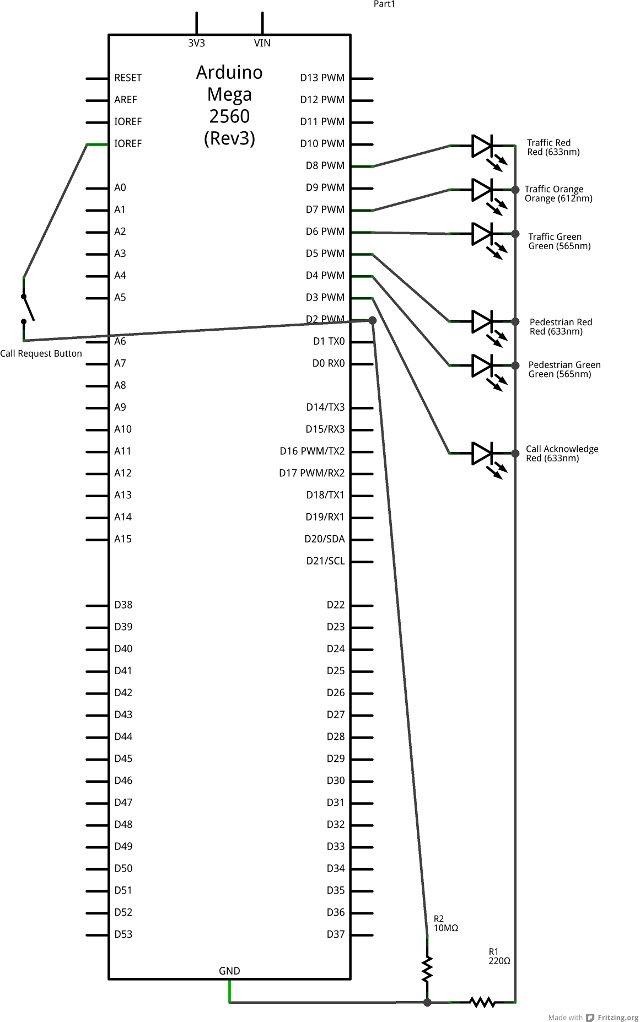
I knocked up a quick proof of concept, installed it and watched it not work. Given I can’t see in infrared, I didn’t know if my circuit was working. I hooked a red LED up in parallel, and it didn’t light up; I thought I had cathode and anode swapped around, so flipped the red LED – and it didn’t light up. I pulled the IR LED, and then the red LED worked… I was shorting out the red LED. I couldn’t – with the bits I had lying around – confirm the device was transmitting anything. Rather than put the LEDs in series, I got a cheap camera-phone with video function, and it could see IR just fine. And it turns out the IR LED was transmitting something, but the WD TV Live media player wasn’t listening. Why?

The NEC infrared control protocol transmits 32 bits in one of two formats, one old (as in elderly) format encodes for 256 devices with 256 commands each, and the other encodes for ~64K devices with 256 commands each. The first 16 bits encode the device, and the second 16 bits encode the command. 16 bits for one of 256 commands, you ask? Well, one byte of the second 16 bits is the command, and the other is – for error checking purposes – the one’s complement of that. Further details of the pulse timing and protocol contents are available in various places, but they neglect to mention the extended addressing format. There are many IR control protocols. To use Ken’s IR library you need to know which protocol is used (which the google search revealed), and you can determine the protocol from the timing data found in the LIRC definition of a protocol, in this case the LIRC infrared control protocol for WDTV Live media player remote. The LIRC protocol defintion format is described by WinLIRC, so you can see what the timings are. In this case, the NEC protocol is revealed by the header, one and zero definitions, along with the fact that each code has 16 bits of ‘pre-data’ and 16 bits of data (a 32 bit package). Everything I could see was showing that the two, separately arrived at sets of command codes that were empirically sampled from the real world were compliant with the spec. One of the things the spec taught me was to transmit the NEC code twice, and to wait 70ms between re-transmissions.

I wasted time finding other codes for the remote, in other formats; I checked for byte ordering issues. Nothing worked.

The actual problem was the unsigned long for the command was previously an int; failing to notice this simple error led me to spend a long time trying to figure out why nothing was happening when I transmitted a command. One of the problems with the C language is the guarantees about data sizes aren’t worth much.  My entire life has been spent programming on architectures that have 32 bit data words; C compilers on these machines have all defined an int as 32 bits, but I’ve always been aware that the language spec says that an int is at least as wide as a short, which is at least as wide as a char with actual widths being up to the compiler implementation (although why you’d have different words for things of the same size is beyond me).  The AVR microcontroller in question has an 8 bit word; mathematical operands typically yield an 8 bit result (multiply is an exception) with compilers needing to implement more instructions to yield greater data widths. The defines express the codes as four byte values, which were then wrangled into a two byte int, and then again into unsigned four byte integer when passed to the IR library. Truncated bits in a protocol like this were the cause of inactivity.

Even with this fundamental problem solved, confusion was added by the fact that one of the memory cells in my Arduino is faulty. Once IR control code transmission was working, I noticed that sometimes it didn’t work. I decided to echo the command to the serial port, and the command being transmitted didn’t match that for the key pressed – the second byte was wrong. I added code to work around this memory corruption (not shown in the code below, because this is a pretty unusual). I’ve never come across this kind of problem before, recognising and then solving something like that is pretty old-school.

/*
Pin 3 is hard-wired into the IR library as the emitter
 */
#include <IRremote.h>
//#define DEBUG

IRsend irsend;

#define btn_enter  0x219E10EF
#define btn_right  0x219E906F
#define btn_left   0x219EE01F
#define btn_down   0x219E00FF
#define btn_up     0x219EA05F
#define btn_option 0x219E58A7
#define btn_back   0x219ED827
#define btn_stop   0x219E20DF
#define btn_rew    0x219EF807
#define btn_ff     0x219E7887
#define btn_play   0x219E50AF
#define btn_prev   0x219E40BF
#define btn_next   0x219E807F
#define btn_eject  0x219E08F7
#define btn_search 0x219EF00F
#define btn_home   0x219E609F
#define btn_power  0x219E48B7

// Pin 13 has an LED connected on most Arduino boards.
// give it a name:
const int onboard_led = 13;
const int retransmit=2;
unsigned long play_after=0;

void setup()
{
  pinMode(3, OUTPUT);     
  pinMode(onboard_led, OUTPUT);     
  Serial.begin(9600);
  Serial.println("WDTV Live serial controlled IR remote");
  Serial.println("~ Power    Eject ^ & Search   Rew - + FF");
  Serial.println("  w         Back q e Enter   Play  P");
  Serial.println("a s d (Arrows)     x Stop    Last < > Next");
  Serial.println("3 - FastForward three minutes");
}

void loop() {
  unsigned long cmd=0;
  if (Serial.available()) {
    switch (Serial.read()) {
      case 'E':
      case 'e':
      case ')':
      case '0':
      case 'O':
      case 'o': cmd=btn_enter; break;
      case 'q':
      case 'Q': cmd=btn_back; break;
      case 'P':
      case 'p':
      case ' ': cmd=btn_play; break;
      case 'S':
      case 's': cmd=btn_down; break;
      case 'W':
      case 'w': cmd=btn_up; break;
      case 'A':
      case 'a': cmd=btn_left; break;
      case 'D':
      case 'd': cmd=btn_right; break;
      case '-':
      case '_': cmd=btn_rew; break;
      case '=':
      case '+': cmd=btn_ff; break;
      case ',':
      case '< ': cmd=btn_prev; break;
      case '.':       
      case '>': cmd=btn_next; break;
      case '/':
      case '?': cmd=btn_option; break;
      case '~': cmd=btn_power; break;
      case '!':
      case '1': cmd=btn_home; break;
      case '^':
      case '6': cmd=btn_eject; break;
      case '*':
      case '8': cmd=btn_search; break;
      case 'x':
      case 'X': cmd=btn_stop; break;
      case '3': 
        if (!play_after) play_after=4; break;
    }
  }
  if (play_after > 0) {
    if (cmd) {
      play_after=0;
    }
    else if (play_after > 5) {
      if (play_after < millis()) {
        cmd=btn_play;
        play_after=0;
      }
    }
    else {
      cmd=btn_ff;
      if (--play_after == 0) {
        play_after=millis()+12000;
      }
    }
  }
  if (cmd) {
    digitalWrite(onboard_led, HIGH);   // turn the LED on to indicate activity
    for (int i = 0; i < retransmit; i++) {
      irsend.sendNEC(cmd, 32);
      delay(70);
    }
#ifdef DEBUG
    Serial.println(cmd, HEX);
#endif
    digitalWrite(onboard_led, LOW);    // turn the LED off - we're done transmitting
  }
}

In other links, How-To: IR Remote Control your Computer

Traffic light and pedestrian crossing implemented with an Arduino


This video shows the Traffic light and pedestrian crossing I’ve implemented with an Arduino. It’s a reproduction of the crossing near my home, timings taken from a video of it.

Pedestrian light_bb

Incidentally, I produced the diagrams for this using a product called Fritzing.  It’s a nifty piece of software that allows you to draw a breadboarded version of your circuit, lay out the circuit schematic and then automatically design the artwork for a etched circuitboard. I haven’t experienced the latter, because of an autoroute bug in version 0.8 of Fritzing.

I exported the images as SVGs from Fritzing and discovered that WordPress won’t allow them to be uploaded because of security issues; presumably the ability to include JavaScript inside a SVG for animation (etc).  So then I exported as PNG, the lossless format.  One of the two images wouldn’t upload, but was acceptable to WordPress after scaling down. I started out publishing on the web using notepad and FTP, and look where I am now.

Hardware

Circuit diagram for pedestrian lights controlled by an AVR microcontroller

I’ve been using an Arduino Mega2560 as the development environment but I’m targeting something smaller for implementation. The code compiles (on the bulky Mega instruction set) to 3.5Kb, so I’m satisfied that as things stand I’m not going to blow any memory budget.

The LED lights all share a single 220 ohm current-limiting resistor, and the call button is pulled low with a 47K ohm resistor to prevent the input pin from floating all over the shop when the button isn’t pressed.

You may notice that the video doesn’t exactly match the diagram. That’s because it’s built out of bits and bobs I had lying around. The ~200-ish Ohm resister had leads that wouldn’t insert into the breadboard. Thus, alligator clips all over the place.

Software

The light cycle is handled with a state machine; the flashing of lights is effected via state changes. The state machine is triggered by interrupts; the ISRs (Interrupt Service Routines) are lightweight, with the “heavyweight” processing for the state machine occurring in response to changes made in the ISRs. To minimise the processing load in the buttonpress ISR a test has been cached in a variable.  The timer ticks over every half second, giving the state machine a half-second resolution – which seems to match what happens in the real world.

The state machine is initialized into a safe state of having the traffic face a red light, and the pedestrians facing the flashing red man.  That means if the system restarts in the middle of a crossing cycle, no one gets killed.

Although the timer is fired via an interrupt, it won’t fire during a delay() so the delay in the main loop is very short.

Although the environment gives an opportunity to develop an OOP solution, their wasn’t any clear need for that level of abstraction, and microcontrollers tend to feel the additional cost of indirection. For example, accesses to members of the state were costly in terms of instructions and lead me to consider using multiple single dimension arrays, accessed by pointer.

#include <TimerOne.h>
//#define DEBUG
/*
Simulate a pedestrian crossing

An Australian pedestrian crossing has three traffic control lights, 
two pedestrian control lights and a light to acknowledge "call requests" 
(i.e. pressing the crossing button).
The traffic control lights cycle red -> green -> amber, solid in all.
The pedestrian control lights cycle red -> green -> flashing red.
The crossing button lights up the call request light, which stays lit
until the pedestrian control light turns green.
Once the traffic control light turns green, it stays that way for some time
before it will yield to a call request.  This is to ensure the road is not
continuously blocked servicing pedestrian crossing needs.

This code responds to two events: the passage of time and the pressing of
the call request button.  Outside of responding to these events the program
has no secondary task.  To optimize the performance of the CPU in its
secondary task, the primary tasks occur in response to interrupts.
*/
// Pin allocation:
const int CallbuttonPin = 2;        // the "I want to cross" button
const int lightCallAcknowledge = 3; // the light that says "you pressed the button"
const int lightGreenMan = 4;        // Pedestrian "walk now"
const int lightRedMan = 5;          // Pedestrian "Do not start walking"
const int lightGreen = 6;          // Traffic go
const int lightAmber = 7;          // Traffic stop if safe
const int lightRed = 8;            // Traffic stop
const int timerPin1 = 9; // lost to timing, can't be used for IO
const int timerPin2 =10; // lost to timing, can't be used for IO
const int onBoardLED = 13;      // on board, can be over-ridden or even cut

typedef struct {
public:
  byte timer_length; // How long to stay in this state (1 tick = 500ms)
  byte action;  // state to set the lights to
  char next_state_on_timer;
  char next_state_on_call_button;
} StateTransition;

const int bitClearCallButton = B00000100; // Clear call acknowledge
const int bitGreenMan =        B10001000; // "walk now"
const int bitRedMan =          B00010000; // "Do not start walking"
const int bitGreen =           B00110000; // Traffic go
const int bitAmber =           B01000000; // Traffic stop if safe
const int bitRed =             B10000000; // Traffic stop
const int maskControlLights = 
            bitGreenMan | bitRedMan | bitGreen | bitAmber | bitRed;

const char NoTransition = -1;
const StateTransition state[] = {
  {8,  bitAmber|bitRedMan,  1, NoTransition},  // Amber and Red Man (4 seconds)
  {4,  bitRed|bitRedMan,    2, NoTransition},  // Red and Red Man (2 seconds)
// Red light lasts for 28 seconds total - 56 ticks
  {21,  bitRed|bitGreenMan|bitClearCallButton,  
                            3, NoTransition},  // Red and Cross
// 7.5 Seconds of flashing red man                            
  {1,  bitRed|bitRedMan,    4, NoTransition},  // Red and Flashing Red Man
  {1,  bitRed,              5, NoTransition},  // Red and Flashing Red Man
  {1,  bitRed|bitRedMan,    6, NoTransition},
  {1,  bitRed,              7, NoTransition},  // 2s
  {1,  bitRed|bitRedMan,    8, NoTransition},
  {1,  bitRed,              9, NoTransition},  // 3s
  {1,  bitRed|bitRedMan,   10, NoTransition},
  {1,  bitRed,             11, NoTransition},  // 4s
  {1,  bitRed|bitRedMan,   12, NoTransition},
  {1,  bitRed,             13, NoTransition},  // 5s
  {1,  bitRed|bitRedMan,   14, NoTransition},
  {1,  bitRed,             15, NoTransition},  // 6s
  {1,  bitRed|bitRedMan,   16, NoTransition},
  {1,  bitRed,             17, NoTransition},  // 7s
  {1,  bitRed|bitRedMan,   18, NoTransition},
  {1,  bitRed,             19, NoTransition},  // 8s
  {9,  bitRed|bitRedMan,   20, NoTransition},  // Red and Red Man
// Allow at least 25.5 seconds of traffic through
  {51, bitGreen|bitRedMan, 21, NoTransition},  // Green and Red Man
  {99, bitGreen|bitRedMan, NoTransition,  0},  // Green and Red Man  // Loop if button pressed
  {1,  bitRed|bitRedMan,    3, 3},  // initial state
};
volatile char current_state = 16;
volatile char next_state = 3;  // Start in a safe state:
volatile byte ticks_remaining = 1;
boolean call_button_disabled = true;

void transition_to_next_state()
{
#ifdef DEBUG
  Serial.print((int)current_state);
  Serial.print(" transitions_to ");
  Serial.println((int)next_state);
#endif
  if (next_state == NoTransition) return;
  current_state = next_state;  
  next_state = NoTransition;

  // turn on the lights as per this state
  byte mask = B00001000;
  byte light=lightGreenMan;
  while (light < = lightRed)
  {
#ifdef DEBUG
    Serial.print("light pin ");
    Serial.print(light);
#endif    
    if (state[current_state].action & mask)
    {
      digitalWrite(light, HIGH);  // turn on the signal
#ifdef DEBUG
      Serial.println(" HIGH");
#endif    
    }
    else
    {
      digitalWrite(light, LOW);  // turn off the signal
#ifdef DEBUG
      Serial.println(" LOW");
#endif    
    }
    light++;
    mask = mask << 1;
  }

  // Turn off the call acknowledge light if that's something we do
  call_button_disabled = state[current_state].action & bitClearCallButton;
  if (call_button_disabled)
  {
#ifdef DEBUG
    Serial.println("CallButtonDisabled()");
#endif    
    digitalWrite(lightCallAcknowledge, LOW);  // turn off the signal
  }

  // start the timer until the next state
  ticks_remaining = state[current_state].timer_length;
}

void timer_tick()
{
  if (--ticks_remaining == 0)
  {
    next_state = state[current_state].next_state_on_timer;
  }
  // See if we can service any existing call
  else if (digitalRead(lightCallAcknowledge))
  {
    next_state = state[current_state].next_state_on_call_button;
  }
}

void call_button_pressed()
{
  // Don't acknowledge if it would be cleared
  if (!call_button_disabled)
  {
    digitalWrite(lightCallAcknowledge, HIGH);  // Acknowledge the request
  }
}

// the setup routine runs once when you press reset:
void setup() {
#ifdef DEBUG
  Serial.begin(9600);
  Serial.println("Traffic light simulation");
#endif    
  pinMode(CallbuttonPin, INPUT);     
  pinMode(lightCallAcknowledge, OUTPUT);     
  pinMode(lightGreenMan, OUTPUT);     
  pinMode(lightRedMan, OUTPUT);     
  pinMode(lightGreen, OUTPUT);     
  pinMode(lightAmber, OUTPUT);     
  pinMode(lightRed, OUTPUT);     
  Timer1.initialize(500000);         // initialize timer1, and set a 1/2 second period
  Timer1.attachInterrupt(timer_tick);  // attaches callback() as a timer overflow interrupt
  attachInterrupt(0, call_button_pressed, CHANGE);
}

// the loop routine runs over and over again forever:
void loop() {
  if (next_state!=NoTransition)
  {
    transition_to_next_state();
  }
  delay(50);
}