
This video shows the Traffic light and pedestrian crossing I’ve implemented with an Arduino. It’s a reproduction of the crossing near my home, timings taken from a video of it.
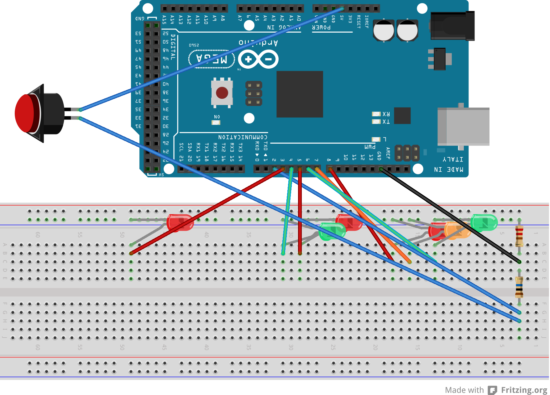
Incidentally, I produced the diagrams for this using a product called Fritzing. It’s a nifty piece of software that allows you to draw a breadboarded version of your circuit, lay out the circuit schematic and then automatically design the artwork for a etched circuitboard. I haven’t experienced the latter, because of an autoroute bug in version 0.8 of Fritzing.
I exported the images as SVGs from Fritzing and discovered that WordPress won’t allow them to be uploaded because of security issues; presumably the ability to include JavaScript inside a SVG for animation (etc). So then I exported as PNG, the lossless format. One of the two images wouldn’t upload, but was acceptable to WordPress after scaling down. I started out publishing on the web using notepad and FTP, and look where I am now.
Hardware
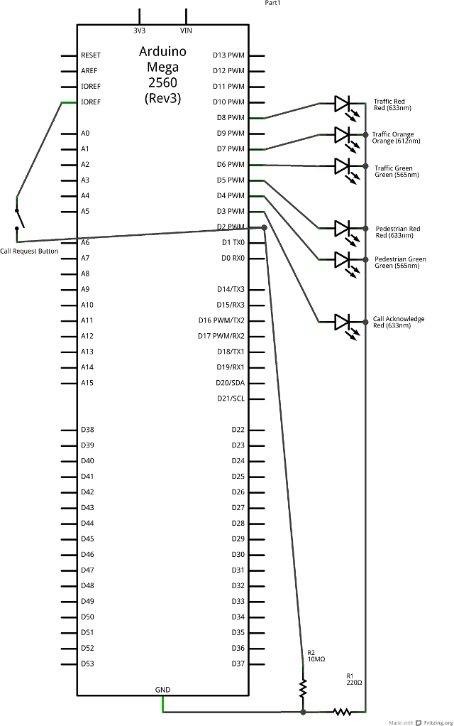
I’ve been using an Arduino Mega2560 as the development environment but I’m targeting something smaller for implementation. The code compiles (on the bulky Mega instruction set) to 3.5Kb, so I’m satisfied that as things stand I’m not going to blow any memory budget.
The LED lights all share a single 220 ohm current-limiting resistor, and the call button is pulled low with a 47K ohm resistor to prevent the input pin from floating all over the shop when the button isn’t pressed.
You may notice that the video doesn’t exactly match the diagram. That’s because it’s built out of bits and bobs I had lying around. The ~200-ish Ohm resister had leads that wouldn’t insert into the breadboard. Thus, alligator clips all over the place.
Software
The light cycle is handled with a state machine; the flashing of lights is effected via state changes. The state machine is triggered by interrupts; the ISRs (Interrupt Service Routines) are lightweight, with the “heavyweight” processing for the state machine occurring in response to changes made in the ISRs. To minimise the processing load in the buttonpress ISR a test has been cached in a variable. The timer ticks over every half second, giving the state machine a half-second resolution – which seems to match what happens in the real world.
The state machine is initialized into a safe state of having the traffic face a red light, and the pedestrians facing the flashing red man. That means if the system restarts in the middle of a crossing cycle, no one gets killed.
Although the timer is fired via an interrupt, it won’t fire during a delay() so the delay in the main loop is very short.
Although the environment gives an opportunity to develop an OOP solution, their wasn’t any clear need for that level of abstraction, and microcontrollers tend to feel the additional cost of indirection. For example, accesses to members of the state were costly in terms of instructions and lead me to consider using multiple single dimension arrays, accessed by pointer.
#include <TimerOne.h>
//#define DEBUG
/*
Simulate a pedestrian crossing

An Australian pedestrian crossing has three traffic control lights,
two pedestrian control lights and a light to acknowledge "call requests"
(i.e. pressing the crossing button).
The traffic control lights cycle red -> green -> amber, solid in all.
The pedestrian control lights cycle red -> green -> flashing red.
The crossing button lights up the call request light, which stays lit
until the pedestrian control light turns green.
Once the traffic control light turns green, it stays that way for some time
before it will yield to a call request.  This is to ensure the road is not
continuously blocked servicing pedestrian crossing needs.

This code responds to two events: the passage of time and the pressing of
the call request button.  Outside of responding to these events the program
has no secondary task.  To optimize the performance of the CPU in its
secondary task, the primary tasks occur in response to interrupts.
*/
// Pin allocation:
const int CallbuttonPin = 2;        // the "I want to cross" button
const int lightCallAcknowledge = 3; // the light that says "you pressed the button"
const int lightGreenMan = 4;        // Pedestrian "walk now"
const int lightRedMan = 5;          // Pedestrian "Do not start walking"
const int lightGreen = 6;          // Traffic go
const int lightAmber = 7;          // Traffic stop if safe
const int lightRed = 8;            // Traffic stop
const int timerPin1 = 9; // lost to timing, can't be used for IO
const int timerPin2 =10; // lost to timing, can't be used for IO
const int onBoardLED = 13;      // on board, can be over-ridden or even cut

typedef struct {
public:
  byte timer_length; // How long to stay in this state (1 tick = 500ms)
  byte action;  // state to set the lights to
  char next_state_on_timer;
  char next_state_on_call_button;
} StateTransition;

const int bitClearCallButton = B00000100; // Clear call acknowledge
const int bitGreenMan =        B10001000; // "walk now"
const int bitRedMan =          B00010000; // "Do not start walking"
const int bitGreen =           B00110000; // Traffic go
const int bitAmber =           B01000000; // Traffic stop if safe
const int bitRed =             B10000000; // Traffic stop
const int maskControlLights =
            bitGreenMan | bitRedMan | bitGreen | bitAmber | bitRed;

const char NoTransition = -1;
const StateTransition state[] = {
  {8,  bitAmber|bitRedMan,  1, NoTransition},  // Amber and Red Man (4 seconds)
  {4,  bitRed|bitRedMan,    2, NoTransition},  // Red and Red Man (2 seconds)
// Red light lasts for 28 seconds total - 56 ticks
  {21,  bitRed|bitGreenMan|bitClearCallButton,
                            3, NoTransition},  // Red and Cross
// 7.5 Seconds of flashing red man
  {1,  bitRed|bitRedMan,    4, NoTransition},  // Red and Flashing Red Man
  {1,  bitRed,              5, NoTransition},  // Red and Flashing Red Man
  {1,  bitRed|bitRedMan,    6, NoTransition},
  {1,  bitRed,              7, NoTransition},  // 2s
  {1,  bitRed|bitRedMan,    8, NoTransition},
  {1,  bitRed,              9, NoTransition},  // 3s
  {1,  bitRed|bitRedMan,   10, NoTransition},
  {1,  bitRed,             11, NoTransition},  // 4s
  {1,  bitRed|bitRedMan,   12, NoTransition},
  {1,  bitRed,             13, NoTransition},  // 5s
  {1,  bitRed|bitRedMan,   14, NoTransition},
  {1,  bitRed,             15, NoTransition},  // 6s
  {1,  bitRed|bitRedMan,   16, NoTransition},
  {1,  bitRed,             17, NoTransition},  // 7s
  {1,  bitRed|bitRedMan,   18, NoTransition},
  {1,  bitRed,             19, NoTransition},  // 8s
  {9,  bitRed|bitRedMan,   20, NoTransition},  // Red and Red Man
// Allow at least 25.5 seconds of traffic through
  {51, bitGreen|bitRedMan, 21, NoTransition},  // Green and Red Man
  {99, bitGreen|bitRedMan, NoTransition,  0},  // Green and Red Man  // Loop if button pressed
  {1,  bitRed|bitRedMan,    3, 3},  // initial state
};
volatile char current_state = 16;
volatile char next_state = 3;  // Start in a safe state:
volatile byte ticks_remaining = 1;
boolean call_button_disabled = true;

void transition_to_next_state()
{
#ifdef DEBUG
  Serial.print((int)current_state);
  Serial.print(" transitions_to ");
  Serial.println((int)next_state);
#endif
  if (next_state == NoTransition) return;
  current_state = next_state;
  next_state = NoTransition;

  // turn on the lights as per this state
  byte mask = B00001000;
  byte light=lightGreenMan;
  while (light < = lightRed)
  {
#ifdef DEBUG
    Serial.print("light pin ");
    Serial.print(light);
#endif
    if (state[current_state].action & mask)
    {
      digitalWrite(light, HIGH);  // turn on the signal
#ifdef DEBUG
      Serial.println(" HIGH");
#endif
    }
    else
    {
      digitalWrite(light, LOW);  // turn off the signal
#ifdef DEBUG
      Serial.println(" LOW");
#endif
    }
    light++;
    mask = mask << 1;
  }

  // Turn off the call acknowledge light if that's something we do
  call_button_disabled = state[current_state].action & bitClearCallButton;
  if (call_button_disabled)
  {
#ifdef DEBUG
    Serial.println("CallButtonDisabled()");
#endif
    digitalWrite(lightCallAcknowledge, LOW);  // turn off the signal
  }

  // start the timer until the next state
  ticks_remaining = state[current_state].timer_length;
}

void timer_tick()
{
  if (--ticks_remaining == 0)
  {
    next_state = state[current_state].next_state_on_timer;
  }
  // See if we can service any existing call
  else if (digitalRead(lightCallAcknowledge))
  {
    next_state = state[current_state].next_state_on_call_button;
  }
}

void call_button_pressed()
{
  // Don't acknowledge if it would be cleared
  if (!call_button_disabled)
  {
    digitalWrite(lightCallAcknowledge, HIGH);  // Acknowledge the request
  }
}

// the setup routine runs once when you press reset:
void setup() {
#ifdef DEBUG
  Serial.begin(9600);
  Serial.println("Traffic light simulation");
#endif
  pinMode(CallbuttonPin, INPUT);
  pinMode(lightCallAcknowledge, OUTPUT);
  pinMode(lightGreenMan, OUTPUT);
  pinMode(lightRedMan, OUTPUT);
  pinMode(lightGreen, OUTPUT);
  pinMode(lightAmber, OUTPUT);
  pinMode(lightRed, OUTPUT);
  Timer1.initialize(500000);         // initialize timer1, and set a 1/2 second period
  Timer1.attachInterrupt(timer_tick);  // attaches callback() as a timer overflow interrupt
  attachInterrupt(0, call_button_pressed, CHANGE);
}

// the loop routine runs over and over again forever:
void loop() {
  if (next_state!=NoTransition)
  {
    transition_to_next_state();
  }
  delay(50);
}
I had to do this for a project back in high school 23 years ago – create a simulation of a nearby intersection using a BBC computer (which were awesome for interfacing). I remember going as far as creating an error trap that flashed the lights amber if my code crashed, good fun 🙂
Interesting. Perth crossings have a flashing amber phase for the vehicles that starts a few seconds after the pedestrians have been given the flashing red. This allows cars to proceed if all the pedestrians have finished crossing.
Certain crossings have that here too; it depends on what the traffic engineers decided at the time. Current thinking is that crossings with a cycle involving flashing amber intimidate pedestrians (“Hurry up, hurry up!”) and lead to more dangerous driving (taking off while there are still pedestrians, for example).
Interesting, you’d think that would be consistent and standard. Here in SA flashing amber only occurs if law enforcement activate it or there is a system fault.
Some pedestrian crossings in the city have recently been upgraded so they show a green walking man for a short while, then changes to yellow digits that count down approximate 25 seconds of remaining crossing time, then the usual red man (no blinking).
Pingback: Traffic light and pedestrian crossing implemented with an Arduino -Use Arduino for Projects